记录学习k230的过程
25.11.11 准备工作、学习摄像模块
准备工作
- 固件烧录
- 例程复现
- 找到了ocr(文字识别)现成例程
小声:结合多平台教程文档,如01studio或嘉楠等等,这个没有的例程,另一个说不定有呢
摄像模块
- k230摄像头架构
- 板子最多搭载三个摄像头
- 每个摄像头可以接入三个不同的处理模块(对输入图像进行加工处理)
- 每个模块(camera_device)有三个输出通道,可以多输出并行
- 摄像头模块编程
-
sensor基础语法
- 创建处理模块
1
2
from media.sensor import * sensor = Sensor(id ,width ,height ,fps) # 实例化,对应架构中的处理模块- id:摄像头id,默认为2
- width ,height ,fps:最大输出图像参数
- 设置图像输出大小和位置
1 2 3 4sensor.reset() # 初始化sensor对象及传感器 sensor.set_framesize(chn=CAM_CHN_ID_0, width=640, height=480) sensor.set_framesize(chn=CAM_CHN_ID_3, framesize = Sensor.VGA)- framesize参数对应width、height,表示输出图像分辨率,二者作用相同。
- framesize = Sensor.VGA即表示640*480分辨率,除此之外,还有Sensor.HD等表示分辨率的代号,这些代号统称为图像帧尺寸
- chn:channel_number,表示输出通道,即架构中每个模块的三个输出通道
- 设置图像怎么输出、输出位置
sensor.set_pixformat(pix_format, chn=CAM_CHN_ID_0)- pix_format:输出图像的像素格式,即每个像素在计算机中如何存储,也就是RGB三个通道数据用多少位存储。
常用有:
RGB565:R for 5 bits ; G for 6 bits ; B for 5 bits
RGB888: R G B for 8 bits respectively
- 水平与竖直反转
sensor.set_hmirror(True) # 水平 sensor.set_vflip(False) # 竖直- 启动、关闭摄像头
  sensor.run()
  sensor.stop()
多个摄像头只用启动一次,但要分别关闭
- 指定通道截一帧图片
sensor.snapshot(chn=CAM_CHN_ID_0)默认为0设备0通道
25.11.13 GPIO
GPIO
-
原理明确
- 硬件之间的通信必须经过通信协议,常用的通信协议有IIC\SPI\UART\CAN\HTTP等等
- 这些“通信协议”是一种规则,在硬件上的体现为实现信息收发的逻辑电路,可以作为模块嵌入到MPU芯片里。
当然,不是所有的协议都软硬兼修,HTTP协议就是纯软件协议
- 通过设置外设的状态,及外设对应的寄存器的值,实现与外界的交互。
例如将某引脚(GPIOA_1)设置为输入模式,然后访问指定端口 GPIOx 的 输入数据寄存器(IDR)的值,看引脚的值为高电平还是低电平,外界传给中央的信号(斜体的部分由
GPIO_ReadInputDataBit函数完成) -
名词解释
- P-mos N-mos:三极管,作用相当于受电压控制的开关,它俩区别是,P为低于阈值导通,N为超出阈值导通
- 串口:特指UART协议的硬件电路部分,信息流向:
MPU ——> 引脚 ——> 串口(片内外设的一种) ——> 外接设备(片外外设) (一个串口可能会用到许多引脚)- 外设:片内外设:通信协议等硬件的逻辑电路模块,本质上是把数据、奇偶校验、等等一系列的流程集成到一个电路模块上,可以装在芯片内部;片外外设:与芯片连接的模块,在芯片外面
-
GPIO干嘛用的?
四大功能:输入、输出、模拟、复用- 输入
- 片内外设向MPU输入
- 分类
- 下拉输入:无外部输入信号时,MPU读到低电平,只有外部输入为高电平时,MPU才能读到高电平
- 上拉输入:无外部输入信号时,MPU读到高电平,与上面同理
- 悬空输入:引脚的电平状态完全由外部输入决定
- 模拟输入:能接受模拟信号,通过ADC(模数转换器)转为数字信号,传递给MPU
- 输出
- MPU向片内外设输出
- 分类
- 推挽输出:P-mos、N-mos均工作(不同时工作),可以主动输出高、低电平。
- 开漏输出:只有N-mos工作,只能主动输出低电平,输出高电平要靠上拉电阻拉上去(内部或者外部的上拉电阻都可以)
# micropython from machine import Pin pin = Pin(index, mode, pull=Pin.PULL_NONE, drive=7)machine.Pin:控制引脚的输入输出状态
index: 引脚编号
mode:Pin.INPin.OUT
pull: 控制内部上下拉电阻,阻值很大,用于稳定芯片内部逻辑电压PULL_UPPULL_DOWNPULL_NONE(默认)
drive: io驱动能力,默认为7- 复用
- 此时GPIO像一个容器,可以对应连接到MPU内部的IIC、SPI、UART等协议的硬件模块,所谓通信协议的硬件模块,本质上是把数据、奇偶校验、等等一系列的流程集成到一个电路模块上,也就是通信协议的物理层面实现,随后该引脚与片外外设通过对应的协议通信。
- 一个GPIO不能同时连接多个协议模块,故要通过编程选择。
- **k230芯片共有63个引脚,开发版上可复用引脚有40个,编写代码时用到的pin_index是芯片上引脚的序号,芯片上引脚与开发板上引脚的GPIO序号通常是一致的,例如,
fpioa.set_founction(3, FPIOA.UART0_TXD)这里的3在芯片上为第三个引脚,在开发板上为GPIO3。如果某个芯片引脚的序号在GPIO上没有对应的序号,则说明这个引脚可能被其他外设占用了(比如串口的GH1.25-4P座子) - 需要注意的是,GPIO和UART、IIC等功能是并列的,由
fpioa = FPIOA()
fpioa_1 = FPIOA()
fpioa.set_function(UART_TX_PIN, FPIOA.UART2_TXD)
fpioa_1.set_function(3, FPIOA.GPIO3)
定义.而某个引脚被定义为GPIO后,使用
machine.Pin模块定义GPIO的输入、输出、上下拉、驱动能力等-
输出模式
Pin.OUT时,指推挽输出。推挽输出时上下两个mos管都可以工作,通过上下两个mos管的接入与否直接决定引脚电平高低,体现在编程上是pin.value(1)或pin.value(0)来设置引脚电平,而drive参数用于量化mos管的“拉力”有多强(正相关),不需要通过内部或者外部的上下拉电阻来控制引脚电平。以点亮LED灯举例,外部电路从VCC出发,经过电阻、LED二极管、另一端接到引脚。故该引脚配置为高电平时,两边都高,断路;反之通路,电流由外部灌入芯片,故称灌电流。推挽输出模式下,引脚电平高低与PULL的模式无关,故PULL设置为PULL_NONE.PULL用于设置芯片内部上下拉电阻状态,该电阻很大,故产生的电流很小。当为开漏输出时,上mos管不能工作,只能输出低电平,则需要一个上拉电阻来产生高电平。这个上拉电阻可以是内部的,即设置PULL为PULL=PULL_UP,也可以是外部的。譬如上例中的LED灌电流,外部电路的VCC是一个很有力的上拉力量,远大于PULL的内部电流,故此时PULL的状态不一定要为上拉,也能正常工作。 -
既然都讲到LED了,简单写一些重要的事项。首先,k230的LED没有使用pwm引脚,不能控制亮度,故rgb值设置为0.5和1是没有任何区别的,都是点亮状态。
 1
 2
 3
 4
 5
 6
 7
 8
 9
10
11
12
13
14
from machine import FPIOA fpioa = FPIOA() # 实例化 # 查看引脚信息 fpioa.help() # 所有引脚的详细信息 fpioa.help(1) # 引脚1的详细信息 fpioa.help(1,func=False) # 同上 fpioa.help(1,func=True) # 功能1的详细信息(功能编码在 [这里](https://wiki.lckfb.com/zh-hans/lushan-pi-k230/basic/gpio-fpioa.html) # 复用 fpioa.set_founction(3, FPIOA.UART0_TXD) # 把第3个引脚复用为串口0的TX脚 fpioa.get_pin_num(FPIOA.UART0_TXD) # 哪些引脚被配置为UART0_TXD fpioa.get_pin_func(63) # 查看63号引脚的被配置为什么功能- 模拟
- 通过输入、输出模式配置、电平高低变化模拟通信协议,即把硬件外设的功能通过软件模拟了一遍
k230的GPIO引脚没有adc,不能模拟
-
总结
- GPIO四大功能:输入、输出、模拟、复用
- GPIO可编程,体现为其模拟功能。
25.11.15.
- GPIO各功能代码示例
25.11.19. UART发送ocr结果
原理明确
-
不同level的电子设备是不同的圈子,圈子间遵循的通信协议不一样。电脑间遵守USB协议,而嵌入式中一般遵循UART/TTL协议。
-
信息的本质是电压变化,TTL(Transistor-Transistor Logic)将电压变化转变为一串0-1信号,而UART(异步串行通信协议)将这串0-1信号按规则进行组织,譬如组织为
起始位–数据位–校验位–终止位
-
随后将组织好的信号传输出去,对面再按这个规则解密就好啦!当然,这是同一圈子内通信
-
不同圈子之间通信就要涉及硬件电路了,结合之前片内外设的定义,用硬件电路实现通信并不难理解。比如电脑和单片机间的通信就要通过usb转ttl模块来完成。
k230端发送数据代码
点击展开查看 OCR 源码
|
|
-
更改说明
- 代码在0-1studio官方ocr例程上改动,更改了主程序部分,添加工具函数
send_ocr_data - 串口定义
- 发送逻辑(主函数):
捕捉当前帧 ——> 推理识别 ——> 满足发送条件(时间间隔)——> 发送
- 分辨率变化流:
Sensor input (1920*1080) —> Pipeline (rgb888p:640*360) —> orc_dec input(640*640) —> orc_rec input(512*32) —> output(640*360) —> send (1920*1080)
- stm32接收到一个坐标和对应的字符串,它需要确定这个坐标数字在实际视野中的位置,也就是比例,故需要事先告诉stm32视野的范围为多少,也就是send时发送的坐标所使用的坐标系(也就是分辨率),它可以为任意(即通过主函数中转换坐标部分实现),声明清楚接受到的数字的“地图边界”是几,即可计算比例与转动角度。
- 代码在0-1studio官方ocr例程上改动,更改了主程序部分,添加工具函数
-
代码心得
-
找到代码逻辑:
- 从主函数开始看,搞懂每一行的作用,并链接到哪个模块实现了这个功能
- 对各个模块,也就是各个类、实例、方法总体浏览一遍,搞懂每个模块的作用,一句话写注释
- 参数传递(重要!) 模块之间层层嵌套,要理清爽数据流(输入数据经过哪些模块、哪些处理,变成怎样的输出)。分清形参和实参,别被名字骗了
-
有一些逻辑是打包封装好的,譬如Pipeline中的pl.create(),这种背后的工作流就会藏得很深,慢慢修炼吧~
-
26.1.28. 基于颜色色块识别实现地图识别
1. 语法解释
img = sensor.snapshot()
blobs = img.find_blobs([black_threshold], pixels_threshold=500, merge=True, margin=15)
-
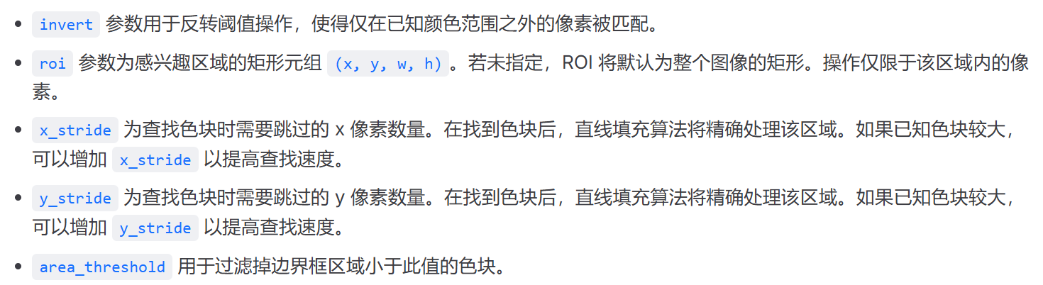
img.find_blobs:寻找色块的函数- 参数
[black_threshold]:列表,其中每个元素是一个元组,例如black_threshold = (0, 20, -10, 10, -10, 10),用于定义目标颜色的检测阈值,分别描述这个颜色对应的LAB的最大最小值
可以包含多个颜色,也就是多个元组,寻找时取并集,并自动对每种颜色二进制编码,例如:
- 匹配了第一个阈值的色块,code = 1 (二进制 $2^0$)。
- 匹配了第二个阈值的色块,code = 2 (二进制 $2^1$)。
- 匹配了第三个阈值的色块,code = 4 (二进制 $2^2$)。
应用时使用CanMV IDE的阈值编辑器确定阈值,达到:目标颜色为白色,其余全部为黑色。滑动阈值调整时会发现,对于六个中的每一个参数,满足目标黑白二值状态的值是一个范围,注意不要取这个范围的端点,因为端点值处于识别变化的临界,易受到外界的干扰,鲁棒性低。要取范围中间的值。
pixel_threshold:像素阈值,检测到的总像素小于这个值的色块将会被过滤merge:合并色块,合并所有没有被过滤的色块。margin参数存在时,还要求这两个色块之间最靠近的像素点距离 $\le$margin此时函数返回的对象就是合并后的大色块
若一个色块同时包含了两种颜色(比如你把红苹果和绿叶子合并成一个大色块),这个大色块的code是其中颜色的code之和,它的 code 就会变成 $1 + 2 = 3$。你可以用blob.code()查看
常用的参数就是这些,下面是其他参数
- 输出
函数返回一个list:
[(x, y, w, h, pixels, cx, cy, rotation, code, count, area, density),(),()...],这个list的每个元素是一个对象,每个对象有这些属性:- rect:
blob.rect()描述颜色块的(x,y,w,h):左上角坐标、width、hight - pixels:
blob.pixels()或blob[4]色块中的像素数 - cy cx:x和y的中心点
- rotation:目标在画面中是横着的( $0$ 或 $\pi$)、竖着的($\pi/2$ 约 1.57)还是斜着的。
- code:颜色编码
- count:合并为该色块的多个色块的数量。只有在调用 image.find_blobs 时设置 merge=True,此数字才会大于1,注意和颜色无关
- area:返回色块周围边框的面积(计算方式为 w * h)
- density:实心色块检测时,密度越小,检测准确度越小 $$Density = \frac{Pixels(色块实际像素点数)}{Width \times Height(外接矩形的面积)}$$
- rect:
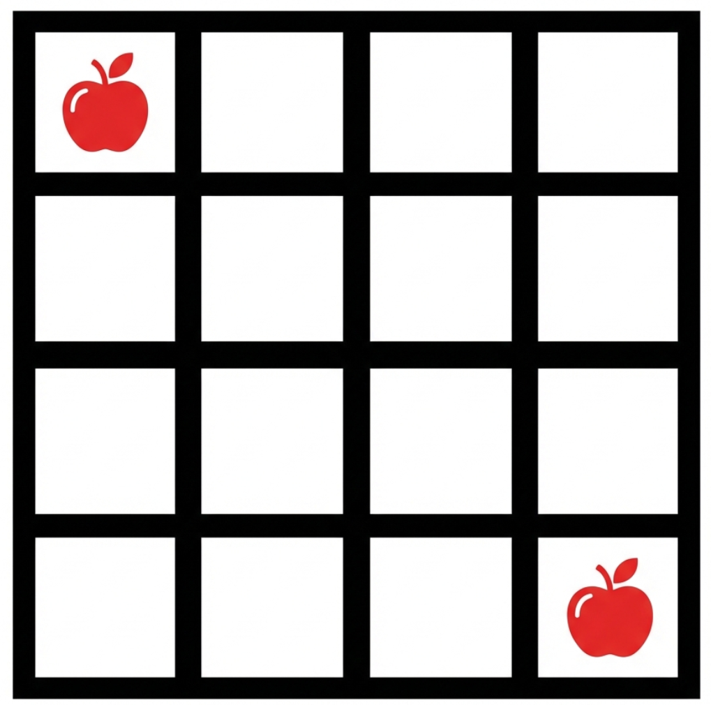
2. 举例:定位水果位置
点击展开查看源码
|
|
结果
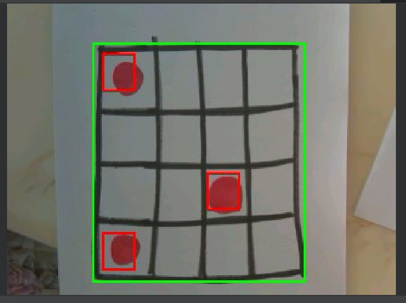
- 原理
- 定位黑色外边框:
blobs = img.find_blobs([black_threshold], pixels_threshold=500, merge=True, margin=15)为什么只识别外边框,忽略内部网格? 首先,寻找黑色矩形,在这里是黑色边框,由于pixels_threshold=500的限制,只有最外层大边框内的像素满足条件。
其次,merge=True,因为网格线间的空白大于15像素,所以合并的是边框上的像素块,但合并后形成的roi覆盖边框及以内的全部区域,而内部小区域被覆盖,故结果仅识别最外层边框